


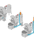
Quick-Connect Kits for MCR-20
Our Quick-Connect Kits for the MCR-20 offer a way to quickly connect your roaster, chaff collector and stand-alone cooling tray fan and arrange your exhaust lines to make it efficient for your installer to connect to termination outdoors. Kits incorporate quick-connect clamps that allow you easy access to inspect your exhaust system and disassemble parts for easy and frequent cleaning.
- Layouts are compatible with MCR-20 with and without the optional green coffee loader
- Our kits are designed for current models of MCR coffee roasters. If you have a previous generation model, contact us to get the correct kit.
- If you've already taken delivery of your roaster, some field measurements may be required to size your adapters.
- Made in the USA
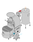
Layout A
| General | Layout requires owner to install two exhaust lines to termination. One 8” (20cm) vent line to accommodate roaster exhaust exiting from chaff collector and one 4” (10cm) exhaust line to accommodate cooling tray exhaust exiting from cooling tray fan. |
| When to use | - Thru-wall exhaust terminations where exhaust lines diverge (ie. high and low) |
| End connection | Owner to connect directly to chaff collector and cooling tray fan. Short disconnect adapters are available for purchase if owner-provided venting does not offer a disconnect adapter. Contact Mill City Roasters. |
| Layout A benefit | Lower initial cost |
| Layout A drawback | - Cooling fan location may limit hopper filling from right side - More complicated for installer on site which may result in higher overall installation cost |
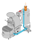
Layout S
| General | Layout requires owner to install two exhaust lines to termination. One 8” (20cm) vent line to accommodate roaster exhaust exiting from chaff collector and one 4” (10cm) exhaust line to accommodate cooling tray exhaust exiting from cooling tray fan. |
| When to use | - Thru-wall exhaust terminations where exhaust lines run parallel. |
| End connection | End of kit above chaff collector includes a Transition Adapter on the 8” (20cm) vent line to connect to owner-provided venting beyond chaff collector. No Transition Adapter is included on the 4” (10cm) cooling tray vent line but is available free of charge if requested at time of kit purchase. |
| Layout S benefit | - Dedicated lines for roaster exhaust and cooling exhaust reduce potential airflow issues |
| Layout S drawback | Two building envelope penetrations |
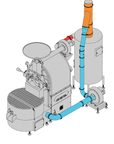
Layout G
| General | Layout requires owner to install one 8” (20cm) diameter exhaust line to accommodate both exhaust lines that have been ganged together in kit. |
| When to use | Thru-roof terminations (straight up through roof). |
| End connection | End of kit includes a Transition Adapter to connect to owner-provided venting beyond kit. |
| Layout G benefit | - One exhaust line to termination required |
| Layout G drawback | Requires high ceiling and roof penetration |
Layout A sizes & clearances
| MCR-20 | MCR-20 with Loader | |
| Assembled size (w x d) | 5’-6” x 10’-5” | 9’-3” x 10’-5” |
| Clearances required | ||
| Working clearance | 36” (1m) required at front & left side of assembly | |
| Non-working clearance | 6” (.15m) if perimeter is non-combustible. If perimeter is combustible, clearance to combustibles below will govern. | |
| Clearance to combustibles* | 18” (.45m) | |
| Combustible flooring clearance | Components installed using standard legs/feet may be installed on combustible flooring. | |
| Minimum space required (w x d - includes combustible clearances noted above) | 10’-0” x 14’-11” | 15’-3” x 14’-11” |
| Minimum ceiling height** | 8'-8" (2.64m) | 8'-8" (2.64m) |
| Top of chaff collector | 5’-4” (1.63m) | 5’-4” (1.63m) |
* If municipality allows, owners can use IMC/ICC Reduction Tables 308.4.2 to reduce clearance required to combustibles.
** Owner-provided venting beyond Quick-Connect Kits may require additional ceiling height. Verify with owner-provided venting specifications.
Layout S sizes & clearances
| MCR-20 | MCR-20 with Loader | |
| Assembled size (w x d) | 5’-3” x 10’-5” | 9’-3” x 10’-5” |
| Clearances required | ||
| Working clearance | 36” (1m) required at front & left side of assembly | |
| Non-working clearance | 6” (.15m) if perimeter is non-combustible. If perimeter is combustible, clearance to combustibles below will govern. | |
| Clearance to combustibles* | 18” (.45m) | |
| Combustible flooring clearance | Components installed using standard legs/feet may be installed on combustible flooring. | |
| Minimum space required (w x d - includes combustible clearances noted above) | 9’-9” x 14’-11” | 15’-3” x 14’-11” |
| Minimum ceiling height** | 8'-8" (2.64m) | 8'-8" (2.64m) |
| Top of Quick-Connect Kit Layout S | 5’-8” (1.78m) | 5’-8” (1.78m) |
* If municipality allows, owners can use IMC/ICC Reduction Tables 308.4.2 to reduce clearance required to combustibles.
** Owner-provided venting beyond Quick-Connect Kits may require additional ceiling height. Verify with owner-provided venting specifications.
Layout G sizes & clearances
| MCR-20 | MCR-20 with Loader | |
| Assembled size (w x d) | 5’-3” x 10’-5” | 9’-3” x 10’-5” |
| Clearances required | ||
| Working clearance | 36” (1m) required at front & left side of assembly | |
| Non-working clearance | 6” (.15m) if perimeter is non-combustible. If perimeter is combustible, clearance to combustibles below will govern. | |
| Clearance to combustibles* | 18” (.45m) | |
| Combustible flooring clearance | Components installed using standard legs/feet may be installed on combustible flooring. | |
| Minimum space required (w x d - includes combustible clearances noted above) | 9’-9” x 14’-11” | 15’-3” x 14’-11” |
| Minimum ceiling height** | 10'-0" (3.04m) | 10'-0" (3.04m) |
| Top of Quick-Connect Kit Layout G | 8’-6” (2.59m) | 8’-6” (2.59m) |
* If municipality allows, owners can use IMC/ICC Reduction Tables 308.4.2 to reduce clearance required to combustibles.
** Owner-provided venting beyond Quick-Connect Kits may require additional ceiling height. Verify with owner-provided venting specifications.